 The initial
support pipe removal was fairly easy. Just remove the two screws holding the
"wings" on the deck and smack the pipe base a few times. The upper
portion is held by a three inch bolt and a PVC pipe cap the factory used as a
spacer.
The initial
support pipe removal was fairly easy. Just remove the two screws holding the
"wings" on the deck and smack the pipe base a few times. The upper
portion is held by a three inch bolt and a PVC pipe cap the factory used as a
spacer.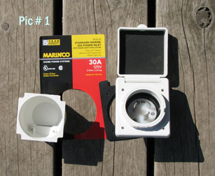
Have you ever tied up at a dock and found out they offer shore power? Think about the home goodies you could be using if that power could be tapped into! The Santana 2023's do not come prepped from the factory with a hookup so I thought I put one in just for one of those times.
The first thing I did was to plan what I think I'll be needing. Maybe I'll put in a battery charger and bilge pump for the essentials. Then I'll add some "nice to have" items like a stereo radio and followed that with a few neat things like a computer.
After the basic list was planned out, I figured about how much power I'll be needing. Not much, maybe 10 amps in my case.
Now I looked at what was available at most of the marinas. Those that have larger boats and near larger cities, seem to have 120 volts AC @ 30 amps and 50 amps. Many smaller marinas have only 120 volts @30 amps.
Small dockage areas that are out in the boonies that often only have dockage for about a dozen boats and normally only provide 120 volts @20 amps. Some of the small remote docks don't have any shore power at all, but they don't matter.
I'm pretty well assured to have 120 VAC @30 amps which is what I went with. If I travel to other areas, that's most likely what I'll find since it's becoming a standard in many locations.
Everything seems pretty straight forward. Just poke some holes in the boat, run some wires and switches, mount a few things, then plug things in.
Someone in the factory, (See picture #1), thought things out! They have a simple template printed on the packaging that's perfect for the main hole.
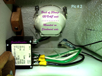
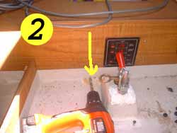
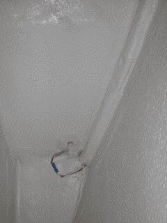
After drilling out the main outlet hole, I made sure to apply and seal, any of the exposed wood core. That included the small screw holes too. (See picture #2)
In another article, I made extra shelving. The starboard was just an inclosed box which I origionally planned a year ago to hold and cover the electricity locations.
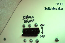
On the outside of the cabin "box", you'll see where I mounted a 30 amp switchbreaker. It's really a 31.25 amp breaker but who's counting. (See pic's #2 & #3)
My switchbreaker is a gang of three. Should any one of the lines trip and kick-out, all three wires will break. This action is the proper method. If one line blows the breaker and the others don't break also, a small amount of voltage/amperage could still be available to do nasty things to your body. There are other circuits that can protect someone's body, but this is probably one of the most positive.
From the "Box", I ran three 12 gauge wire to the same area that holds the battery. Each wire has an oil proof covering. At the battery area had put a few AC rated switches for use later. I say later because I don't have the other items that use AC power mounted in my sailboat yet! (Hey... its coming!)
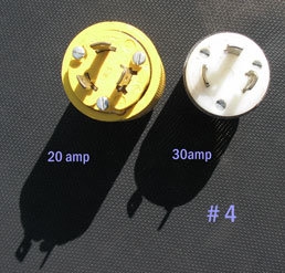
Now that I have a good 30 amp outlet, I also picked up a couple 30 amp plugs. Please be very careful and be extra sure the male and female plugs are really for 30 amps. If you look at picture #4 where I have both size plugs, 20 and 30 amp, you'll notice that both look nearly identical. Don't mix them up! Should you have both sizes at home, you can just read the inscription that states what they are. If you think they are interchangable, think twice!
Photo #4 shows a 20 amp and 30 amp plug from two different manufactures. They look like the prongs are the same but trust me when I tell you they aren't. The 20 amp plug is just the thickness of the blades smaller than the 30 amp plug. Read the plug end for the correct size. They won't fit if you confuse and mix then up.
Since I had already removed my mast support pipe while rebedding the mast base, I decided to also run my mast electrical wires inside the pipe instead of being tie-wrapped to the outside of it. That will make the cabin look better and prevent scratching my skin while going forward.
The initial
support pipe removal was fairly easy. Just remove the two screws holding the
"wings" on the deck and smack the pipe base a few times. The upper
portion is held by a three inch bolt and a PVC pipe cap the factory used as a
spacer.
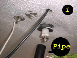
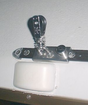
 Picture #1 shows
what I found under the pipe top after removal. You'll note the white and the
black wires going through the overhead. Remember that I had run the two wires
that way earlier.
Picture #1 shows
what I found under the pipe top after removal. You'll note the white and the
black wires going through the overhead. Remember that I had run the two wires
that way earlier.
Starting from the top of what is under the pipe, you see the mast base plate
which is enclosed within most of the fiberglass, then comes a rubber washer
(which just happens to be the same size as the rubber washer plug on the water
ballast valve, then a snug spacer (made from a drilled out PVC cap), then a
regular stainless steel washer, and finally a 3/8th inch stainless Nyloc nut.
Everything is tightly held together by a 3/8th" x 3" bolt. You just
happen to see the other end every time you setup for raising the mast on the
outside.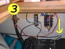
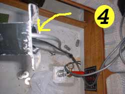
Setting the wires aside, I then drilled two small holes to fit the wires through the storage bulkhead. (See #2) The holes are low enough to have the wires run under the carpet and in my case, lay right next to the cabin-side water ballast valve section.
Picture #3 shows the inner area. Note how close the holes are to the battery. Be careful not to drill the battery it self!
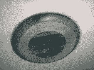
 After filing a
cave-like hole at the mast support base, I pulled the wires up and then out the
upper holes I pre-drilled at 3" from the top. This does not show the
cave-like hole well but trust me when I say it's directly behind the wires.
After filing a
cave-like hole at the mast support base, I pulled the wires up and then out the
upper holes I pre-drilled at 3" from the top. This does not show the
cave-like hole well but trust me when I say it's directly behind the wires.
 The wires were
pulled with cord I had previously run down inside the pipe. The upper two
holes, were drilled 3" from the top. This was done to make room for the
spacer plug.
The wires were
pulled with cord I had previously run down inside the pipe. The upper two
holes, were drilled 3" from the top. This was done to make room for the
spacer plug.
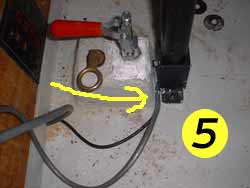
Replacing the pipe, I reassembled everything with a new rubber washer and decided to add a large SS washer so the pipe wouldn't slowly dig it's way through the rubber like the original had done. Then I tightened everything, rebed the mast support base area, slid the pipe back in place, and tightened the two screws. (See picture #5.)
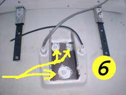 Seen in picture #6
is the wires coming out the top deck and the bolts holding the mast base. The
wires and bolt heads were coated with 3M's 4000 UV seal just because I felt
like doing it.
Seen in picture #6
is the wires coming out the top deck and the bolts holding the mast base. The
wires and bolt heads were coated with 3M's 4000 UV seal just because I felt
like doing it.
 After I was happy
with everything, I covered the wires with plastic cover. (It has a natural slit
in it so I could encase the wires afterwards.)
After I was happy
with everything, I covered the wires with plastic cover. (It has a natural slit
in it so I could encase the wires afterwards.)
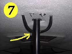
Remember earlier I mentioned having to drill the upper holes three inches from the top. This shows how it looks as a finished product.
As I was doing this project, I kept thinking about how it is like a natural lightning grounding route.
Should the mast get zapped; the strike would travel through the mast base, easily going through the thin rubber washer, down the pipe and likely burn a hole as it traveled to the water ballast valve rod, and finally exit out the water ballast area. Either by the water in the tank or by the bottom of the rod, or both!
An interesting thought that and it is like that for every 2023 made.
Many owners seem to be confused about the navigational lights needed for our 2023 sailboats. In an attempt to clarify things, I've linked to a "Boat Safe" web page to show what is needed. The copies are taken directly from a Federal Regulation booklet that can be obtained at many boating stores.
The booklets are provided by the USCG Auxiliary and USPS and are free of charge. That being so, you have no reason not to have a copy in your boat! In the worst case you can't get to a boating store, send me your snail-mail address and I can send a copy to you.
Go to this site and reference the figure numbers I have mentioned below. http://www.boatsafe.com/nauticalknowhow/boating/4_2_b.htm The stock lighting configuration on a Santana 2023, is shown in figure #3, (left).
It also does not have dayshapes as stock accessories. You'll need to purchase them separately if desired.
It's important to remember that Santana 2023's are just over 7 meters long. Others may talk about using a flashlight or lantern but we fall into figure #7, not figure #6. That also means with the stock lighting configuration you will not be legal to either anchor or motor at night, (or during times of limited visibility). If you plan on doing any of this, you'll need to change things around.
1) If you're Sailing (or rowing); reference figures #3, #4, or #5 only.
(Repeating; #3, (left), is the stock configuration on a 2023. Should you decide to change your lighting; figures #3,(right), #4, or #5 could be used.)
2) If you're Anchored; reference figures #7 and #8.
3) As soon as you fire-up that "Iron Genny" hanging off the stern you become a powerboat. Reference figures #1, (left), or #9, (right). Note that if motoring outside of inland waters, the dayshape must be displayed. Reference #9, (left).
Many sailors purchase and install a different light set for each requirement. I'd like to but financially it's another story! Being of limited funds, I have come up with a simple way to meet all legal requirements.
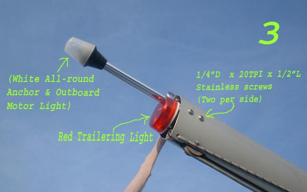
The first thing needed is to mount a proper anchor light on top of your mast. For illustration purposes I borrowed a picture from my "Trailer Information" section. (That's why it's listed as #3.)
The anchor light will also serve as an all around light when you're motoring at night, or during times of limited visibility, (along with the red/green bow light). Reference #2 on the linked site.
You now have enough "lights" to sail, motor, or anchor at night, (or times of limited visibility). Now all needed is a good way to turn on the proper lighting configuration when called out for.
The simplest way is to have switches for all lights separately. One switch for the bow light, one for the anchor light, and one for the stern light. Then all you have to do is flip the proper ones on or off.
If you've not already noticed, I like to figure things out. In this case I'm working on a three-switch setup for everything. It's just not done yet! I guess that means this article is still "Under Construction", (for now!)
The Legal description of navigation lights are actually in points instead of degrees. 32 points being 360 degree of the compass.
The stern light is one white light at the stern, so constructed that it shall show an unbroken light over an area of the horizon of 12 points of the compass.
From the bow, the white steaming light actually shines 10 points on the starboard side and 10 points on the port side starting from the bow. (Similar coverage as the red/green bow lights.)
All the running lights combined, total 32 points. The anchor light also shines 32 points. That makes it possible someone looking towards you at night can see a light, of some kind, no matter which way you're pointing.
The factory ran the stern-light wires directly behind the rub rail. They may have epoxied over them on the inside, I don't really know . In the picture, you'll see the port through-bolted stern rail and the rear light wires feeding into it. As you already know, except for most of the wires, everything has been covered with sprayed gel coat.
The wires for my electric start 9.9 outboard motor were run basically all the way back on the top shelf-like position and about every three feet I pulled a screw and inserted a nylon wire band, then reinserted the screw. This was done to prevent the wires from falling out of their position. I need not worry about the nylon getting sun hardened and brittle for obvious reasons.
Before running the wires through each bulkhead, I had to make a small hole larger by drilling and filing. I also protected the wires from chafing by wrapping a small piece of plastic tube around it. One can never be to sure!
If you feel like installing an electric start motor, it'll take about 25-30 feet to reach from the stern to the battery and about two days of work! All told it took me about a week, that was because of the 90 sunny degrees outside every day and 110+ sweaty degrees in the cramped, wind-less stern section! (Time conflicts prevented evening working.)
Most sailors put their VHF antenna on the very top of their mast. Mine was mounted up there for a year or so but I changed my mind and lowered it a few feet. In doing so I made it more secure and safer by my beliefs.
Knowing the importance of using through-bolts I had previously installed a set for the all important upper shroud and forestay mount. Basically all I did was put the antenna base on the port side of the bolt and added two stainless screws to hold the antenna mount from spinning around. (You can just make out one of the two screws in the picture.)
As for the cable, I drilled a 5/8th inch hole into the mast to allow it access. After hooking the cable and pulling it through the mast, I fit a small rubber grommet around it and fastened it into the mast hole. You'll notice that I put a small loop in the cable. That serves two functions. One is for those occasional rainy times as a drip-loop to prevent water from being fed into the connector, and the second reason is to add a little resistance so the weight of the cable would not pull directly on the connector. A small strain relief if you will, that works well.
The "safety" part also comes in two thoughts. One is because the antenna whip is not sticking real far out the back when being trailered around and because of my beliefs after I read many reports about lightening strikes.
When lightening strikes, it forms a 40 to 45 degree cone from the highest strike location downward. With-in the cone, direct bolts seem to be dispersed and hopefully weakened or eliminated. It may not always happen this way but it seems to.
Mounting the antenna down on the through-bolt allows the tip of the whip to be within the cone's safety area. Plus the aluminum mast doesn't seem to affect either the transmission or reception to any noticeable degree.
One other observation, it seemed that lightening is more likely to hit if your boat is properly lightening protected and less likely on an unprotected one. Although less likely to get hit, should lightening strike an unprotected boat collateral damage is increased.
In other words, a properly protected boat should have far less damage and an unprotected boat could get everything fried and put holes in your hull!
Why does attracting lightening save equipment? It seems that once you've directed the strike, there is less damage done due to side strikes. No one really knows the true route but no lightening protection definitely makes more of a mess.
If you have proper lightening protection that's the best way to go, but if not, try for the possibility of the safety cone effect. (Which is what I did.) Pondering everything is very confusing! If you find it too confusing, lower the antenna as I have and just think of saving the whip from bouncing all over the place as you trailer by wrapping it to the mast!
After looking over several type GPS machine's, I finalized on the Garmin 125 Sounder! It's mounted in my port bulkhead next to the hatch and looks very good.
The 125 works as well as it looks with two exceptions. I lost satellite signal strength once late in the season, maybe the Govt. was messin' around? Another time the sounder portion acted funny, showing over 500 feet in 20 feet of water. That was probably because air bubbles got under the hull in the near six foot chop. The last thing is that over the years the plastic has started to gray. It must not be UV protected.
About the transducer, I purchased a "thorough hull" type. In my opinion it is very large. it's made for a hull thickness from 1 1/2" to about 4". My hull is about 3/8" thick, no way enough. Looking around I came up with a two inch diameter PVC end cap. After poking a drill through the cap, I filed the hole large enough to accept the sounder. This made a spacer that had my thickness problem under control.
The space around the transducer was filled with 100% waterproof aquarium grade silicon seal. Purchased at a pet store, I figured that if it was good enough to hold big fish tanks together in your livingroom, it had to be good enough for my purpose.
The sounder's position is about 2 feet forward of where the mast pole would be on the hull. This puts it a foot below the surface and in relatively clear flowing water. If I ever beach my boat the transducer will probably get sandblasted but as I mentioned earlier the "sounder" is so large I feel it will hold up.
Many other sailers mount there transducer inside the boat and never poke a hole in the hull. Looking back, I now feel I should have at least tried that method to see how it works first. (Less holes in the hull are better!)
When I mounted my GPS antenna the sheet blocks were fastened by the factory in one location per side. Since then I "expanded my abilities" by adding sheet block tracks. That turned out to give me more trouble than one which was properly thought out. Well... at first I thought it was!
The GPS antenna was originally temporarily tried in many locations on my boat. A Garmin tech told me that the antenna had to be facing straight up. Everyplace up that I tried was either directly where you would walk or in a remote location I didn't want to fish the wire to. So I finallized on the port side cabin roof, just below the top. The cabin top sides on the A and R model 2023's aren't as vertical as the C model and proved very easy to run the antenna wire on the inside. Plus it was just a few feet from the unit itself and out of harm's way.
When I added the sheet tracks, the port track came real close to the antenna. No problem I told myself, just put the track a fraction further away to make room for the block's slide mount. (Notice the picture of the right.)
Since putting the track in that location, I've found that sliding in the rear half causes the sheets themselves to foul on the shrouds.
Another problem only happens when the slide is put right by the GPS antenna and then only when I cruise in certain directions which is why I couldn't figure it out at first.
Look at the picture. The slide is steel, the track itself is aluminum and half of the block is steel also. What that means is that when the slide is real close to the antenna, it blocks reception from any satellite in that direction. Everything works fine when I change my course otherwise weak or no coverage is the norm.
Remember what I mentioned about having the antenna near flat? Well it isn't totally flat in mild winds but still works fine. If the winds increase and I lean abit more than I should the antenna starts becoming upside-down. As long as a satellite has a near clear shot to the antenna, no problems. Most of the time all works well it's just when you tip abit over 20 degrees and go in certain directions the Garmin reception starts to act up.
Don't get me wrong I love the Garmin and feel it's an excellent machine, I just have to relocate the antenna somewhere... better. (After calling the company I found out that two antennas cannot be hooked up to one machine. To bad, one on each side of the boat would have solved all my reception problems.)
My radio antenna and anchor light wires are running inside the mast. Near the base I mounted appropriate connectors for when the mast is stored for trailering.
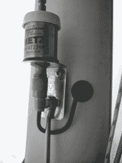
After obtaining a watertight gray colored PVC fitting at my local hardware store, (Cheap at about 3 1/2 bucks for two fittings!), I ran the wires through my deck near the tabernacle. In addition to being inexpensive, they are UV protected, always a plus factor.
*NOTE: If you poke a hole close to the tabernacle, you WILL be drilling through metal inside the fiberglass! If you don't mind that's okay, if you do I suggest three to four inches minimum distance away. *(I drilled right on the edge of the metal. What a pain! The bit kept "walking" to the side.)
The fitting is used for electrical waterproofing and strain relieving wire and has a rubber grommet under the cap. The lower portion has 3/8", (NPT), pipe thread. Once you "tap" a female 3/8" tapered pipe thread into the hole, the fitting will just screw into it. They also come in a larger size, but I only needed the little one for my purpose
To be extra sure about being watertight, I sealed the threads and I put some goop inside the cap to assist the rubber before snugging the cap on. The tighter the cap is screwed down, the more the original rubber gets compressed. I guess it works because I've had no leaks yet.
The sealer I used was regular silicone glue and seal which is available at just about any department store. The picture was taken below my winter blue tarp, (for some reason bird "stuff" is all around). That explains the color and the "dirt" you see. Also remember that silicone needs to be replaced every few years if for nothing else just to make it look better. My seal is about five years old. I think I'll use a better seal this springtime.
If you hook this up to the mast be sure not to make the mistake I did. My connectors are on the front section of the mast. I'll move them to the rear portion of the mast like I should have in the first place. (Having them on the front of the mast just gives the jib sheets a good place to snag.)
My battery is a deep cell type and really doesn't get to much use. Other than my outboard's electric starting motor, GPS, VHF, and the seldom used running lights, there is nothing else. Not knowing the battery condition, I looked into a charger. At first I thought about a fast charger but my past hinted to one that was slower if I wanted the same battery for a longer time.
Several articles explained about chargers and battery use. They all leaned toward keeping the cells cooler while charging and use. In other words, don't discharge too fast or charge too fast. Both will create heat. Heat is what will kill a battery!
After looking around I found that Sears sold the same 1 1/2 amp automatic charger as other marine and auto parts stores only for a few bucks less, right around $26.00 as of 1999. The unit works nice and has a green LED showing the unit being on and a red LED showing when the battery is fully charged up.
*One more thing. Keep the battery on the higher end of being charged. The lower the cells are before charging them back up, the shorter the life will be. If you run the batteries down allot, try looking into getting another battery and/or a solar charger to assist in topping them off. As a last resort and your outboard has a charger built into it, run the motor to keep them up.
![]()
Return to Home Port.
Mail to: The WebCaptain1@yahoo.com