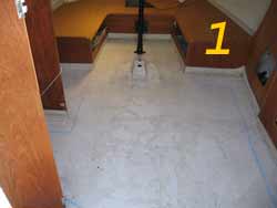
 Pic #1 - The original cabin deck. *The
blue outline indicates the cut-out line.
Pic #1 - The original cabin deck. *The
blue outline indicates the cut-out line.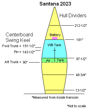
Here's a picture that I received a long time ago.
The data came from a poor quality drawing dated back in 1992.
Remember that all measurements are referenced from the inside of the transom.
The original sheet only indicated where the wooden sections were and where the centerboard trunk started and stopped, and where the CB pin is located. I put in the names and the battery location.
This indicates where the positive flotation chamber is located, (labeled "Air Tank").
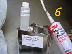
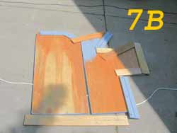
Here are pictures of epoxy coating modification Rudy did on his 1993 "A" model:
Pic #1 - The original cabin deck. *The
blue outline indicates the cut-out line.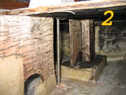
Yea, I know the water ballast valve, (WB), system works just fine when you treat it right, but if you haven't noticed so far, I like to change things! It was just a matter of time before I got around to the WB system. During my seasonal Michigan layover I figured another simple mod was in store.
Pretty simple plug! Simple indeed but I never really liked the constant twirling up and down so a modification was needed to make it "better".
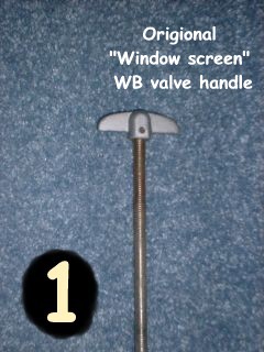
Most of us already know that the wing-nut on top is really a tee nut for a screen window. (See picture #1) To make the continual turning of it easier while opening or closing the WB plug owner Allen has filed a couple slots in a spark plug socket and turns the socket with a speed wrench.
Others have mentioned putting two nuts on top and jamming them together, then using a wrench to turn the shaft. The main thing I don't care for is that I still have to twirl it up and down.
One thing important! If you use any of the above methods, stock hand tightened or wrench tightened, DO NOT over tighten the plug! If the plug ever gets drawn inside the tank it will be very difficult to get it back out.
To remove the rod, you'll first need to back out the set screw in the wing-nut. Once the set screw is loosened, hold the rod with out messing the threads and unscrew the wing-nut for the rod. Now it's just a matter of screwing the rod down about as far as you can. Climb out of the cabin and under the hull then grab the patch-plug and continue unscrewing the rod until it comes out.
Warning! Unless you are planning to use a brand new rubber patch, do not mess the old one up for obvious reasons.
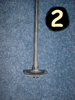
Picture #2 shows how they sandwiched a 2-1/4" diameter by 1/8" thick piece of conveyor belt material between two Nyloc nuts. The upper has a regular washer and the lower has a 1-1/2 inch diameter stainless steel "fender" washer. The washers support the patch which has a layer of cloth-weave molded into the middle. The cloth piece is visible if you look carefully at the edge of the rubber patch.
Picture #3 shows the clamp mechanism. It's a De-Sta-Co brand clamp, model #604 and is availably at some of the more complete hardware stores and at most every industrial part's stores. It gives me about an inch and a half of travel which is plenty to let the water flow freely in and out.
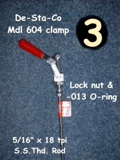
The mechanism I obtained is zinc plated and runs around $14, but they do offer them in stainless steel if you decide to shell out it's price of $36. A very good idea if your heavy into salt water sailing.
Carefully looking at picture #3, you'll see the clamp mechanism with the 5/16" course threaded rod assembled together. To hold them in place I used a 5/16" Nyloc. Also notice that I put a standard buna-N O-ring, (size dash 013), on the lower portion of the clamp "plunger" to assist sealing the clamp-shaft. The O-ring gets slightly squeezed between the Nyloc and the clamp's base. This will prevent any water or air from creeping into the sliding portion of the clamp. I really doubt if it's needed but in theory it's good to have. The red and white manufacture's paper tag on the rod will be torn off before it's installed on my boat.
When the factory put the original valve in, (See lower patch in pic #2), it was able to twist itself into position and self correct for any slight miss-alignment as the patch covered the bottom hole. Now that I switched to a straight push/pull valve, the patch is not able to wiggle it's way directly over the hole. Sounds like a bummer but it really wasn't.
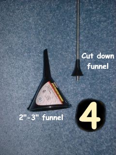
At a local Ace hardware store I obtained a three-pack of small oil resistant plastic funnels for about a buck. With one of the funnels, I made sure the 5/16" rod would not slide through the small bottom portion on it's own. This was because I was going to thread it onto the rod like a nut, (See picture #4). Comparing sizes I ended up using the 3" funnel, the 2" would also have fit.
Having the correct size funnel I marked and sliced off the little end so that I could firmly thread it onto the rod. Now that the small end was threaded, I removed it from the rod so I could work on the big end.
*Side note: You can tap the funnel from the inside to form the threads. That is a hole lot easier than threading it on the rod from the small end! Remove it and put it back on from the small side as shown in pictures 4 & 5.
*Side note: The funnel and the large fender washer will eventually "sandwich" the rubber patch just like the original factory plug was assembled, (See picture #2). The funnel will not be tightened. It will only be snugged as it acts as a cover. Both lower Nyloc nuts will do the hard-core securing of the washers and patch. The funnel will then be screwed down onto the patch.
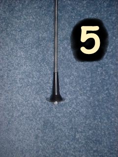
Trimming the large end of the funnel to about 1-1/4" diameter, it will now cover most of the metal fender washer. My funnel is made out of Polypropylene, (Recycling mark of #7), and was slightly brittle as I trimmed the size down. The cut surfaces of the funnel were finished by sanding them flat, (See pictures #4 & #5).
The entire reason of the funnel was to enable the patch to slide into position and positively seal the bottom fill hole. Your sailboat might already have come with a hole that lines up just right with the hull's bottom patch hole. If that's the case, you won't need to do the funnel trick I did!
To assemble the lower portion, screw the modified funnel on the rod a little more than you think should be necessary. After that put a Nyloc nut on. Right-side up or upside down it really won't matter. (If you originally purchased a 36" threaded rod and cut it in half, then the little funnel can be screwed on about four inches from the bottom. One of the Nyloc nuts can be screwed on about an inch less.)
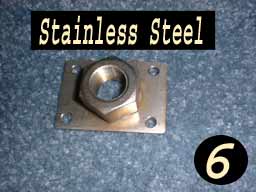
First, get an approximate size for the area of a stainless steel plate and cut it out. (For my "A" model the plate was about 1-1/2" by 2-1/4")
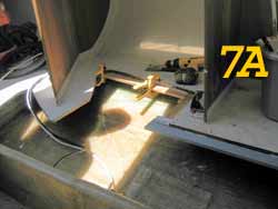
Next, I drilled out four small 3/16" diameter holes towards the corners and a one inch hole in the very center. The stainless steel nut was then welded on the plate over the one inch hole as seen in pictures #6. (My friend did the welding and it cost me two six packs!)
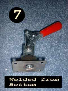
The nut was welded from the bottom, as seen in picture #7. There was no special reason to weld it from the bottom except that I felt water and "humidity" would be more likely to cause trouble from the tank side. That being so, I chose to seal as much as possible from that side.
From the inside, drill out the factory installed nut so the new hole will accept the new plunger/washer/nut assembly. Use a 1" bimetal hole saw drill bit for this. There is no problem drilling through the fiberglass and wood but if you remember, there is also metal in there.
Being one inch you'll have plenty of room for applying a coating of seal or epoxy to protect the inner wood from soaking up water and still have clearance for the washer and nut on the rod to pass through. The plate and nut assembly will be wide enough to cover the hole so the final product will look nice.
Sure, proper seal would be best but I didn't have any handy and didn't feel like buying it, but I did have silicone seal for my bathroom so that is what I used. If any problems occur later it will be a simple matter of lifting the clamp/plate and rebedding it.
The main reason to fasten the entire plate down on the fiberglass using 1/2" stainless screws is to prevent it from twisting or sliding around. To do this, just drill little pilot holes into the fiberglass using the holes in the plate as a guide. Apply seal around the area then lightly screw the entire De-Sta-Co clamp and plate down. Don't forget to secure the 5/16" rod/nut before fastening things down.
One more part to remember is to not lock the large 3/4" nut and prevent the lever from turning. You'll see why later.
*Side Note: After you have drilled out the fiberglass I used a rat tail file to clean up the hole. Don't forget to seal around the hole so the wood core will not soak up water. I guess you could also use something like 3M's 5200 for doing that.
The final assemble is possible to do alone but would be much easier if a second person could assist. If you choose to go-it-alone, you may need to continually climb in and out of your boat. The second person can either works from inside the cabin section or from underneath the hull. (I climbed around three times.)
With the rod with the funnel and one Nyloc already down through the bottom hull hole, you can now turn the lever sideways and you'll find that from under the hull it's a simple matter to grab a wrench and twist the Nyloc into the approximate position needed the properly cover the hull hole.
Follow the lower-inner Nyloc with a regular size stainless washer. Next comes the rubber patch material then the 5/16" x 1-1/2" stainless "fender" washer. Finally the last 5/16" stainless Nyloc goes on. After everything has been properly fit, snug the nuts but don't tighten until a final measurement has been made.
Now check the lever action on the inside and made final nut adjustments for a nice and proper seal with the patch. Tighten the two Nyloc nuts
You'll need to operate the clamp a few times in order to find out how much of the rod needs to be cut off to allow the patch to seal properly. I suggest that you close the clamp from the inside then climb outside and turn the funnel and inner nut up until it's about where it should be. Then open the clamp and raise the outer nut until the patch is snugly held. Just remember not to force anything! (You DO NOT want to draw the plug inside the tank!)
For me there was about three inches of extra rod sticking down beyond the patch. After attaching a pair of Vise-grips at the bottom of the rod, I just hacksawed the extra rod off. (I left one thread beyond the Nyloc so it could be deformed and really hold the nut from falling off.)
*REMEMBER not to make any finish cuts until everything is checked two or three times. It's much easier, (and cheaper), to cut something later than it would be to replace or add length to it later! Now go back inside and a couple drops of oil to all the moving parts of the clamp. Now sit back and play with it while the oil works in.
Now you have the outside patch assemble looking similar to the factory part, (Pic #2), except your now using a 5/16" rod instead of the 3/8" factory supplied rod.

Picture #8 shows the complete assembly with the valve half closed. The red lever goes directly over the air valve plug when the WB plug is closed. *(Don't forget to put a drop or two of oil on the sliding portions of the valve unit.)
Should yo wonder what the black and the white wires are; the black one is for my onboard VHF radio antenna coax wire and the white is for my mast anchor light. Origionally I had them tie wrapped on the outside of the mast support pipe. Soon I'll be re-routing them inside so I won't be scrtching my hand as I grab the bar to move up forward.
Now that everything is matched up and the clamp/lever has been snugged so it won't turn anymore, you'll have a tricked out lever action valve assembly!
Another side note: I hope no one beaches their boat with the water valve open. That goes for the stock factory type also. Should you do this, it's possible to get sand/mud/etc. into the tank in addition to be scraping the rod end on the ground.
Water Ballast Valve Modification parts list |
|||
Item |
Description |
Qty. |
Total(As of Mar 2004) |
| 1a | Clamp, De-Sta-Co, Mdl 604, Zinc Plated | 1 | $14.00 |
| 1b | (You can also obtain the clamp in Stainless Steel.) | (1) | ($35.00) |
| 2 | Threaded Rod, 5/16" x 18tpi, Stainless, 36" long | 1 | $9.00 |
| 3 | Washer, 5/16" ID x 1-1/2" OD, Stainless, Fender Washer | 1 | $0.80 |
| 4a | Washer, 5/16" ID, Stainless, 3/4" OD or less | 2 | $0.24 |
| 4b | (You could substitute with 1/4" ID and file ID to fit 5/16") | (2) | ($0.20) |
| 5 | Nut, Nyloc, 5/16" x 18tpi, Stainless | 3 | $1.05 |
| 6 | O-ring, Buna-N, Standard type, Size -013 (or -905) | 1 | $0.10 |
| 7 | Patch plug, 2-1/4" Dia. x 5/16" ID" x 1/8" thick | 1 | $0.50 |
| 8 | Funnel, 2" or 3" size | 1 | $1.00 or less |
| 9 | Stainless Base Plate (aprox. 2-1/2" by 3" by 1/16" thick) | 1 | Couple bucks |
| 10 | Stainless Steel Nut, 3/4" by 18tpi (very hard to find!) | 1 | Couple bucks |
| 11 | A small touch of lube oil | (Drops) | - |
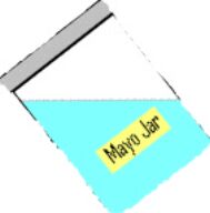
The factory warns to never sail without filling the water ballast, (WB), tank all the way! Why do you think they say that? If you were to take a clean mayonnaise jar and fill it half way with water, screw the lid on tight, then tip it about 45 degrees to the side, what happens? The water remains horizontal to the earth's horizon and the jar has a 45 degree tip. (Duh!)
Using that example should tell you that your boat would tip very easily being that no ballast is trying to hold your boat upright. Play it smart and fill the tank!
"We generally think of air as being weightless. But, the ocean of air surrounding the earth does exert a pressure. Torricelli, the inventor of the barometer, showed that atmospheric pressure could be measured by a column of mercury. Filling a tube with mercury and inverting it in a pan of mercury, he found that a standard atmosphere at sea level could support a column of mercury 29.92 inches high…" (Quoted from my 35 year old hydraulics' textbook.) These are common numbers you might hear from a weather person!
What all that basically means to us is, as long as there is counteracting pressure, It isn't going to flow.
As an experiment, the next time you go to a restaurant, get a drinking straw and push it in your Coke. Now seal the upper open end with your finger. Lift the straw a few inches but not out of the fluid in the cup. You've just made a very crude barometer.
Now lift the straw out of the fluid and hold it there. Note that much of it leaks out. You've just caused an imbalance of pressure and that is what pushed the fluid out. (Except what sticks to the straw itself and other surface tensions, but that's a another story.)
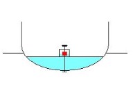
Now that your sailboat tank is properly filled, things change for the better. Note the water in the small box area where you use the crank and air plug.

As the listing becomes greater, the small upper box area, (Where the air plug is located), prevents air from getting into the main portion of the tank. Being that the small box doesn't let the air reach the main WB tank, then the pressures remain constant, (slight differences are not mentioned to keep my explanation simple).
Just like in the Barometer example above, the pressures remain constant and the water cannot be pushed out.
In simple thoughts, you don't really need to plug the air hole, at least not when you don't list very much. One thing to remember, if you tip over too much air will reach the main tank and that will cause a pressure imballance. Water will then leak.
This could happen in ruff weather conditions or by just heavy duty pitching which will cause the water to splash out the hole. Best thing is to plug the air hole and snug the lower seal.
*I'm sure someone can pick my choice of words apart. Basically that is how the water and tank act. Should you notice something that is very incorrect, please let me know! (No one on earth if perfect and it's getting late!)
You'll note that it's a little dirty. There are allot of floating weed towards the end of summer. Guess what gets drawn into the tank? Along with the normal water, just about everything that is close to the opening.
This is one main reason to always add bleach to the tank every time you fill it. Besides weeds, you have egg's, seeds, Zebra mussels, and other assorted nasties that I have no idea even existed!
There's always a small amount of water left inside the tank that can keep the critters alive. Being a trailerable sailboat it's easy to spread them to another body of water. A naturalist once told me that in a stagnant puddle of water it takes at least ten days to kill off Zebra mussels. If you frequent other lakes in less time it becomes imperative for you to add bleach to your water ballast tank.
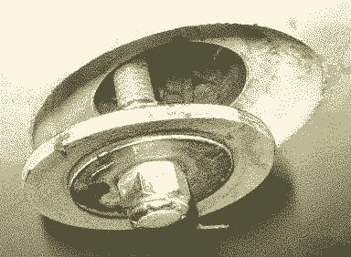
As you see the sealing area is recessed about 3/8" with tapered sides. The taper helps align the plug should it be off set as mine is. The actual gasket/seal is a round piece of conveyor belt-like rubber with an oversize stainless washer (Fender Washer) on the lower side, pinched together by two stainless Nyloc nuts. You can just barely see the inner nut in this picture.
Remember to just firmly snug the patch on the hole. Should you force it future problems could happen. Like drawing the plug inside or messing the threaded portion up at the wing-nut.
This is something no one likes but it happens on occasions... water ballast tank problems. I almost don't want to include this because of the negative thoughts people have. Truth be known, most owners never experience it!
The factory designed the 2023's to be easily trailerable, this means that the WB tank normally gets drained and dries out often. Before approximately 1996, the factory used resin soaked marine plywood to form the WB tanks. Afterwards they made all the 2023's with a fiberglass lined tank.
NOTE: (If you're looking into buying a 2023 sailboat, please know that many pre '96 boats were modified by the factory, a local fiberglass shop, or the owner.)
Those who choose to leave their boat in the water the full season have a greater risk of having the inner wood begin to rot. After three full seasons in the water, one owner began to develope symptoms. Most 2023's are "dry sailed" or trailered and have never shown any problems. As an example; I have not had any problems in over six years. In the future I will find a way to seal my boat's WB tank just because...
Several owners had their rear stringer/bulkhead allow water to seep into the rear air chamber and this is what normally is the first indication of a problem. From that point several others installed small inspection ports to check for any water entry. Some did and some did not find water buildup. Putting the port in permitted many owners to have piece of mind.
Roughly speaking, get inside the tank and apply something to seal it. A bottom coat, the fancy spray or paint-on sealers, on the ends and the underside of the cabin sole. Of course a good fiberglass coverage is best but as long as the seal will stick to wood it should be okay. That seems to be a good cure.
One simple note: remember not to coat the threads on the fill/drain rod with anything except grease.
When Seth glasses his tank, he plan to beef it up by putting fillets of epoxy on the inside corners of the bulkhead cleats and where the deck meets the mast support so that the glass will fit tighter, seal better, and to add strength.
For those who are wondering about what is underneath their mastpole support, owner Seth has provided several great pictures and descriptions.
As previously mentioned, until 1996 the factory used a simple coating inside the WB tank. After several years of water soaking the coating start starts to break-down. My guess is that it is from a combination of things, 1) being it is a thin coating and 2) from expansion/contraction. Looking closer at the pictures you'll see that the base wood is really not bad at all!
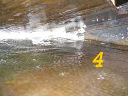
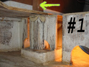
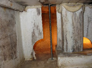
Number one picture is an overall shot of the forward center section of the WB tank. For your reference, I have a yellow arrow pointing to the base of the mast support which you see on the cabin floor.
On the very bottom of the support inside the tank is a 2x8x8 block. The area it covers on the hull is sufficient enough so when the shrouds are tight they don't force the entire mast section through the bottom.
Above that are two 2x4's "sandwiching" the center 1/2" plywood vertical deck support. (Note: besides support they baffle the water, and the "bridge-like" holes to allow proper filling and draining.) Picture #2 gives you a better idea of what I'm talking about.
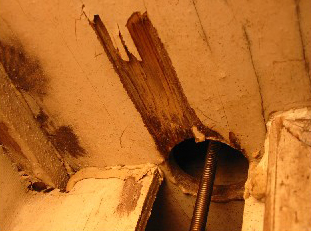
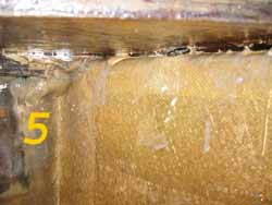
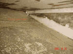
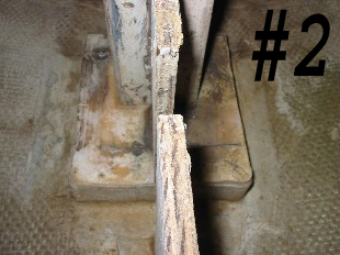
These pictures were taken in the same mast-support area talked about above, only this shows more of the valve rod. After I knocked off some of the brittle, (not even slightly flexible), bedding compound you'll notice the valve hole has no protection from the water.
The hole through the top of ballast tank for the valve stem rod was cut after the deck was treated with polyester.
*(My assumption is; after the factory attached the cabin sole to the hull, they used a hole saw with an extension to drill directly through both at the same time. Another guess is that they drilled from the bottom, (hull side), upward. I only say from that direction because the hull valve molding would allow a great place to center things up and the gap between the vertical plywood would provide nice guide for the drill. That's just a guess.)
Checking was bad around the sole's valve hole and where the table mount base is located. Seth didn't feel the edges of either of these holes were ever treated. This is something everyone should seal properly.
During a phone conversation Seth told me his thoughts about the cause why some water ballast tanks go bad and others don't.
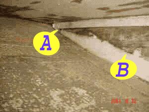
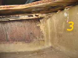
Looking at the picture, notice location "A" & "B". The factory applied tape and fiberglass a couple inches on to the wood. So far no problems.
When you fill the tank everything gets wet. The fiberglass parts don't seem to care but the lightly coated wood parts slowly breakdown to spotty-coated wood. The bare parts are what start to rot and leak. Remember too, hearing that you should "air out" the tank every couple months. Most do or think they do.
When you drain the tank there is always some water remaining inside. After storing on the trailer there is a natural lean towards the rear. That causes the water remaining inside to puddle at the rear.
Looking closer at "A" & "B", you notice the difference in fiberglass overlap-coverage. Should the top of remaining water be over the overlap, much of the wood is soaked for a long time, at least until evaporation lowers the level of water.
In my opinion this is very possible. (Great investigational work Seth!)
When I store my 2023, it is on a slight de-cline and allows all the water to puddle and/or drain to the mid to front. Once much of the water is out and being that I never re-close the drain plug on the bottom, evaporation quickly dries the tank out.
Even with the tongue's prop wheel all the way down so that rain water is able to drain out the cockpit stern drains, it so gradual that I get a slight "slime" buildup in my cockpit. This might be an unknown blessing. So far my 1994 boat has not shown any signs of a bad WB tank.
Seth mentioned that he found an air gap between the sides of the cabin sole and the hull. He also mentioned finding four 1"x1" small wooden blocks near the outer part of the sole that were stapled into the sole. That they may have been used to hold the sole off the ground while the simple polyester resin coating setup and dried. He chose to remove them in his preparations for glassing the tank, (the staples holding them were nasty anyway).
After putting thinking about what he told me, I took a wild guess that the spacers could also have been used to assist in aligning the sole and hull during assemblage. The small air-gap could have deliberately be included. This could, (would?), allow for expansion-contraction without cracking the hull sides. This is a guess on my part. *(If someone could confirm the air gap's reason, it would be appreciated.)
Seth doesn't see much point in glassing the top of the tank if I don't include the last two inches in the seam between the hull and the deck. By the way, there would be no way at all to do so with only inspection ports to work through.
The main other weak points under the cabin floor, are the holes for the table receiver and the ballast valve, which would be easy to deal with by just filleted and glassing the table support section.
The most important places to glass are; (1) the forward and aft bulkheads, where the wood looks worst and wasn't even covered with polyester except for 4" tape strips at the bottom corners (same as inside my under seat bins); (2) the vertical plywood deck support forward of the centerboard housing that is essentially naked except for tape at the hull junction, and (3) glassing together the mast supports would be worthwhile since someone apparently reported a problem with them come apart.
The "stuff" used to coat the ballast tank is very brittle, almost crystalline!
Further reflection about the deck/hull joint. If you look at the top of the joint on your boat (where your cabin floor meets your hull) what do you see? Can that joint flex? Is it cracked? An alternative hypothesis: during construction, the deck was placed on top of the forward and aft bulkheads of the ballast tank, plus whatever is aft of the ballast tank, and, with much now crystallized caulk, on the mast support, center plywood support (with arches), and the centerboard housing. It was fastened from the top to the 1x1 corner strips of the ballast tank bulkheads.
Then the deck/hull seams were filled with polyester and tape from the top side. In this scenario, the bevel on the underside of the deck was to ensure that the deck rested on the fitted ballast tank bulkheads and the centerboard tank, and not its outside edges against the hull. What do you think?
Inspect the deck/hull interface from both sides. If the top side looks rigid, he may proceed with filleting the bottom side, and then covering the seam coating with biaxial fiberglass tape, and following that with woven cloth covering of the deck's underside.
It may not matter but the factory uses "Life Caulk" and "Life Seal" exclusively not 3M's 4200 and 5200 stuff. Personally like the 3M stuff - (it's easier to tell apart at the store in the tubes), plus I really like their relatively new and easy to use 3M-4000 seal for everything short of using the ridged 5200 seal.
![]()
Return to Home Port.
Mail to: The WebCaptain1@yahoo.com