Santana 2023 Owners & Santa Wannabes!
Rigging / Mast
& Sails
Alternative Spreader Assembly
Tom B. had lost a factory mast at the spreader bracket slot and looked for a
better system!
He bought a Dwyer Aluminum Mast
Company, DH2331 Staineless Steel Spreader bracket which they designed for
the Colgate 26, (price in 2008 was $64.90), and two DH2503 large aluminum
airfoil spreaders, (2008 price $31.10). The bracket can be screwed to the mast
or riveted on the factory mast and is considerably stronger than the stock
style.
His assembly was mounted on a new Dwyer mast with standing rigging, (Dwyer
DM330), but it could be adapted to the OEM mast. This is something to consider.
*Note: At the time of writing, (June 2010), the Dwyer website did not show
the DH2331 spreader mount. The number is good but doesn't show in the catalog.
Call or e-mail Jay Kirby at Dwyer,
(mail@dwermast.com), he'll walk you through. You might want to trace the bottom
of the mast profile and send it to him. They may be able to further customize
it for better fit to the 2023 Mast with that info. The bracket is from the
Colgate 26 mast which they make.
Mast Support / Base Rebedding
My 1994 sailboat is celibrating its 11th birthday, (as of 2005), I think its
time to rebed the mast base support!

To start out, I removed the
two phillips head wood screws at the lower "wings" near "A"
of pic #1. Looking at the old seal around that part, I noticed it was abit
cracked and flaky so all I did was to lightly tap it towards the rear to break
it free from the cabin deck. (Should yours be stuck better than mine was, just
cut and/or scrape away as much old seal as necessary to free it up.) Moving the
post further back allowed the post to wiggle down and out of the upper support.
(seen in position "B" of picture #2)
*Just to explain: "B" in Pic #1, denotes the wires that I ran up
my mast. The black one is for my VHF radio antenna and the white one is for my
anchor/mast light. Both wires were originally tie wrapped on the mast support
pole. The nylon tie wraps played havoc on my hands when you grabbed the pole to
go forward. I'll be fixing that soon by relocating them inside the support
pole. "C" is my quarter-throw valve. (Explained in the "Hull and
Water Ballast" page.) "D" is the stock electric panel which I
plan to upgrade soon. (That is also the direction to the bow of the boat.)
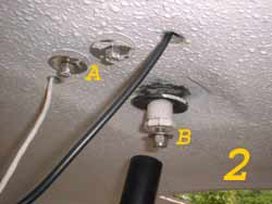
With the lower section
pushed back that lowered the post so it could be wiggled off the upper support.
Seen in picture #2, position "B". (The bolt is a stainless steel
3/8" diameter, 3 inch long, course thread.)
When I removed the post, I found that the black rubber seal on the overhead
was nearly cut in two from the support pole resting on it. It was also noted
how simple the factory made everything. All they did was to use a PVC plug and
drill a 3/8th hole through it. Then they lightly sanded the flats to snugly fit
inside the aluminum 1-1/2" diameter by 45-1/2" long mast support
pole.
After removing the pole I used a 7/16" open end wrench to hold the
outside parts of position "A" while I used a 7/16" socket to
remove the inside nuts. just prior to their removal I lightly tapped them
upward so the bolts could be removed from the outside. In a similar fashion I
removed the 3/8th inch bolt.
The rubber patch look familiar. It was identical to the rubber patch used
for the stock water ballast valve! Should you need one just go to a Tractor
Supply Store (TSC). They have them for about $2.80 as of July 2005.
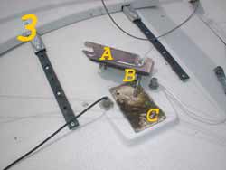
In picture #3 you'll see
the black area that is directly under the outside aluminum mast base support.
That is not a black rubber seal, it was moldy old seal the factory used.
(During rough weather sailing, water was leaking in from that area too.) That
you time and clean every bit of the black scum off. For the final cleaning I
just used fine sand paper. Low and behold, it's white under there!
It's really important for you to remove every bit of the old moldy seal as
when ever you put new on top it will only hold as well as the base coat will
let it.
Being the base coat of seal, (at least on mine), was totally ruined, I
highly doubt water would be held back once the mold starts to infect the new
seal I just put on.
Rebuilding!
Now that everything is cleaned up, I got some 3M 4000 UV seal and first
circled all three holes on top. Then I lightly applied more to cover the rest
of the part the mast base was to cover.
Seeing that the 3/8" hole was tapered and the bolt was not, I obtained
a washer to cover the tapered part of the metal and placed it on the bolt. Then
I lightly put more seal on the lower half of all the bolts making sure I put
just a bit more around the tapered part as the washer was going to cover it.
From inside the cabin I placed the fender washer and nuts on the smaller
bolts and just like when I removed them, I placed an open end wrench on the top
and started to fasten them. DO NOT TIGHTEN THEM! Just put them part way on.
When assembling the 3/8" bolt from the inside, you'll have to put a
rubber washer on first, then go to the hardware store and get a really big
fender washer. (Mine was a 1/2" hole by 2-1/2" fender washer. They
didn't have a really big 3/8" one.) The big SS fender washer goes on next,
then put the PVC plug back on, then the regular 3/8 fender washer, then the
Nyloc nut. Just like before, DO NOT tighten it!
About 20 minutes later, the the 4000 seal has "skinned" over and
you can then tighten all the bolts.
From here it just a matter of a small amount of seal on the clean cabin deck
where the post rests, wiggling the post back in place and snugging the screws
in.
I'm going to put my wires inside the pole before I put the post back in
place so I'll not seal the lower part yet. This entire rebedding takes less
than an hour.
| Description |
Cost (July 2005) |
| Big fender washer |
90 cents |
| 3M 4000UV seal (One small tube) |
$9.00 |
| Rubber patch (At TSC store) |
$2.80 |
|
Less than $15.00 |
Spreader Ends
The spreader are made from aluminum and have a one
inch max outside diameter. The outer ends have a nylon plug pushed in. Mine
came from the factory colored black but over time that will naturally fade and
the nylon will weaken or crack needing replacement.
On the ends of each plug there is a shallow vertical slot or groove and a
hole on each side of the groove that a stainless screw, (two total), goes into.
Another piece of nylon is screwed over the plug, lets call it a cap. It also
has a matching shallow groove. The flat cap acts as a "pinch" device
for the upper cables, (shroud), which fit through the groove.
I hope the descriptions above don't make the spreader tip area confusing or
sound complicated, it's not! Just about anything can be used to hold the
shrouds, the factory used nylon. Over the years that seemed to work very well
and the price is pretty low also.
Spreader Tip UV Protection
Apply rigging tape on the outer portion of the
spreader. That will help stop the UV attack on the plastic spreader tips.
Sheet Purchase Attachment 2:1
(The R models have winches and don't need this setup.)
During the first
couple seasons my wife and daughter both found it very difficult to adjust the
sheets when a load was pulling hard. During a really good blow I did too. They
tried their best from the forward portion of the cockpit. Being close to the
clamps both of them nearly got their hands pinched in the clamps. I always sat
in the rear so as to steer and adjust. The pinching never really crossed my
mine but I wanted to protect them so I modified the stock 1:1 ratio into a 2:1.
Oh yea, I also told them not to be so close to the pinch clamps!
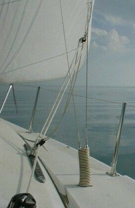
Look carefully at the picture, it shows a two to one sheet setup for the jib
/ genny. This is a poorman's way to get more purchase power on the jib when you
don't have a winch.
Notice that I have added a sheet block track. The track is not needed for
the 2:1 setup nor does it come standard on the A or C models. The 2:1
modification works with or without a track.
The smallest clevis I could find that fit around the clew slot was used to
attach two Harkin blocks on the clew of the jib. (In order to keep flying mass
to a minimum during a tack / jybe. The pulley blocks also reduced the friction
that would be caused by directly going through the clew hole on the jib. One
block is for the port sheet and the other for the starboard sheet.
*(The clew came with a smooth stainless hole. I didn't really need to attach
a block. It's your choice, to use one or not.)
The setup is quite simple. First tie one end of the sheet to the base of the
cabin mounted sheet block. From there fish the other end through the clew hole
or the pulley and back to the original cabin mounted sheet block pulley, then
rearward through the pinch clamp. Don't forget to tie a stopper knot on the end
of the line! The line is about 15 feet longer than originally used for the 1:1
setup.
The factory warns about the possible difficulty for the sheets to be fed
when tacking. Since going 2:1, I have not noticed any problems in winds over a
couple knots.
*In another section I talk about making sure the shroud's turnbuckle didn't
bend when raising the mast during setup. If you look at the picture you'll see
the plastic tube I mentioned using. For lack of any other name my ego got the
best of me and I names it "George's Dual Boot". (You can stop
laughing now because it works!) It's a tube that both shroud turnbuckles are
inside.
Lower Shroud Setup (ball-end fix)
After the first winter layup I inspected everything
the following spring, that included the spreader bars and shrouds. As I looked
at the lower shroud's ball ends, I noticed that both had tiny raised line-like
marks on them. My previous knowledge of mechanical things told me the lines
were created by the tool that squeezed the ball ends on the cable end. The
lines being steel would dig into the softer aluminum spreader bar every time
the mast was raised. Being loose while trailering, the ball ends would
"snag" in a cocked position. As the mast was raised the shrouds would
bend the cable at a variety of directions. The bending back and forth could
possible cause failure as well as being pulled out
Common sense told me to file the "lines" off. Having cleaned them
off, it would give the balls more of a chance to pivot in the bar's socket. The
cable now has less chance to bend and fatigue.
I consider the small bit of filing to be what prevented any problems on my
boat. Now that I think about it, a shot or two of lube might help more. Every
2023 owner should look to see if the crimp-lines are causing problems for them!
The more I think about it, the more I'm convinced the "line" is the
problem and the filing is the fix.
Mast Base Improvement
On the bottom of the mast, you find the two triangle
plates that hold things in place. This also has a bolt to the rear that assists
when stepping.
In four years of mast raising and sailing around, during a regular
inspection, I found the rear bolt and the lower front bolt were wearing more
than I thought they should be so I looked for ways to beef things up. The
picture shows what I came up with.
The bolts are all slightly thin and wore far too much for my likings. Guess
what I did? You've got it, I increased the diameter and I added a compression
washer! (My wife says that I over-kill everything. Sometimes... I do!)
The bolts were suppose to be grade 304 stainless steel or better. When I
hunted around at local stores all I could find were lesser-grades that had a
metric like stamping on the bolt head so no one could tell what they were. Even
the store didn't know what they were. Later I called an industrial supply house
and inquired about the different stamping marks. Eventually I obtained the
correct grade type. The ones I finally got were similar to the required 304 SS.
That made me feel much better.

Mast
Modification
The original two forward bolts were 1/4" in diameter and the rear bolt
was a 5/16". A 5/16" diam. bolt will fit nicely inside 1/2"
diam. grade 304 hydraulic tube that has a wall thickness of .083". That's
a standard size and should be stocked at any good hydraulic tube shop.
After obtaining the parts I drilled and filed the mast's 1/4" holes,
opening them up to fit the 1/2" OD tubing. The 1/2" tubes provided
more surface area which gives me a much longer life.
Mast Plate Modification
The rear holes already fit a 5/16" bolt so I increased them to fit a
larger 3/8" SS bolt. (More overkill? Naaa!)
The last drilling was on the forward holes. They were drilled to fit a
5/16" diam. bolt. This part turned out to be easy just remember; DO NOT
cut and file the bolt ends until after the final finishing. *(Trust me on this
one. Do the final length fitting after everything else has been completed, and
try it several times to be sure! Of course you can just buy additional bolts.)
Remember; THE PLATES were drilled to fit the bolts. (A 3/8" diameter
bolt for the rear hole and 5/16" diameter for the two forward holes.) The
two holes on THE MAST were modified to accept the 1/2" diameter tube
Easy, so you would think. After assembling the plates only, (not mounted on
the mast), I had to file the tabernacle holes and slots to fit the new sizes.
The operation of the plates was to be sure everything would fit while the mast
was lifted into the vertical position. (Important to note this was done while
not being mounted on the mast.) Just pretend your raising the mast and file the
slots so they allow a smooth fit as the bolt/tubes move into position. Be sure
the bolts are tightened to the normal width so the plates will fit properly.
Next I mounted everything on the mast itself. This was done countless times.
On then off. On then off. Just to find out how to get a tight fit on the mast
and still be able to operate on the tabernacle. Now I put four to five
1/2" nylon washers on each side of the front two tubes. This was done so I
could keep everything snug which prevents the mast from sliding on the tubes
and wearing something out. Putting the nylon spacers on took several other
"On and off" actions. (What a pain!)
The next day I raised the mast just like I would at a lake. Yea... I had to
re-adjust the bolts again. After having to purchase another 5/16" bolt, (I
told you to wait until totally finished before cutting the bolt lengths!) Now I
was happy and finished the project by cutting and filing the bolt to a proper
length.
| Oversize mast base bolts. (Use 304 Stainless
Steel) |
Total Approximate Costs (Year=1999) |
| 1 |
4-1/2" x 3/8" NC |
$4.00 |
| 1 |
3/8" Stainless Nyloc nut |
$0.30 |
| 2 |
3/8" Flat Washers |
$0.20 |
| 2 |
5" x 5/16" NC |
$5.00 |
| 2 |
5/16" Stainless Nyloc nuts |
$0.35 |
| 4 |
5/16" Flat Washers |
$0.25 |
| 24 |
1/2" flat nylon washer/spacers (replace with new later on when sun
worn) |
$0.50 |
| 2 |
4" x 1/2" x .083" hydraulic tube. (filing by trail and error
to fit.) |
$5.00 |
| 1 |
Regular 3/8" NC nut (to use for initial fitting & filing) |
N/A |
| 2 |
Regular 5/16" NC nuts (to use for initial fitting & filing) |
N/A |
| 1 |
5/16" drill bit |
N/A |
| 1 |
3/8" drill bit |
N/A |
| 1 |
1/2" drill bit |
N/A |
| - |
(Safely use drill motor, metal files and wrenches as needed.) |
N/A |
| Ruffle cost $15.00 total. |
I'm not really sure but somewhere during this time I filed the tubes so
their length were near perfect. They had to fit between the plates and hold the
plates out enough so as not to cause binding on the tabernacle. The nylon flat
washers were used for the proper spacing.
After finally getting everything to fit in place, I tightened the front
bolts with SS Nyloc nuts. The plates were now snug as a bug and I was happy!
Upper Forestay Through-bolt
Similar as what was done in the "Mast Base
Improvement", I modified the upper forestay bolt by making a compression
bolt for it. The bolt's strength was improved and I was able to mount my VHF
antenna to it, (see electrical section). The bar is needed to mount the upper
furler roller which additionally holds the forestay. Over time, the loose fit
and the constant pulling of the forestay cable caused my bolt to bend.
The only difficult part of this installation was that the compression tube
section needed to be in two sections, one on each side of the aluminum bar.
After several, (many?), fittings of the bolt and modifying the tubes, all
worked out fine.
It really isn't that difficult. The only scary part was when I originally
started to remove the bar from the slot. It wouldn't come out even after
repeated wiggling and pulling. I found the reason. While on top of a ladder
with my head and eye ball real close looking directly into the slot to see if I
could figure the reason. Several wasps slowly started to crawl out of the slot
but couldn't fly. Thank you for the cold Michigan spring time day!
Later and after much wasp spray, I slowly removing the bar I found lots of
wasp nest on it.
Basic Cable Data for My Tall A-model
Santana 2023A - Tall Mast (30') Shroud & Forstay Data
All stainless cables are 1x19 wrap and stock from the factory.
|
Stock Dim's |
Lowers
(inside set, from deck to spreader bar) |
1/8" diam.
14' 2-1/4" long
|
Uppers
(outside set, from deck to mast around spreaders) |
5/32" diam.
27' 0" long
|
Forestay
(mounted between Harkens furler units)
(Mine seemed short so a small amount of spacing was added below the furler
unit.) |
26' 11" long
|
(I'm sure the factory aproximated each cable set by an inch or two. Your
lengths may varie!)
Sheet Clamps
The stock jib sheet clamps were difficult to operate
from the opposite side as they were only made to operate from a near straight
pull. Giving myself a Christmas gift, I replaced them with ones that allow
proper operation from the sides.
Several other owners mentioned changing them to the kind that pivot. All
though the end result is the same I have a problem with the cost. It's nearly
three times the cost than the ones I obtained and the pivot type look like they
might get hung-up on the leeward line. Well... maybe not but why bother
thinking about it anyway.
Gooseneck Improvements - (several methods)
You're enjoying smooth sailing across a beautiful
lake. With a slight wind shift and no other boats around, you figure it's a
great time to tack. Starting your smooth turn it is suddenly interrupted by the
jib sheets, or jib itself, getting fowled on the gooseneck, thus ruining your
placid sail. A major problem... no. A major hassle... yes!
Everyone has talked about this inherent problem. Several owners have come up
with methods to prevent this from happening. Most seem promising but only one
is a sure bet.
| Here are three methods: |
| 1 |
The simplest way
mentioned by Mark |
His trick is to keep both sheets taut during a tack. If your good, things
won't get hung-up much, if not have a nice walk up forward! |
| 2 |
The second best way
told by Steve |
Simply screw in an eyebolt above the gooseneck and attach a bungee cord
from it down to the front deck hatch. That gives the sheets something to
"bounce off". This works most of the time and is very cheap. |
| 3 |
The best and sure fire method!
(see below) |
During my Michigan off season, I designed and built a totally new
gooseneck. This one doesn't stick out the front of the mast at all like the
stock type. When you tack there's nothing to get caught on! |
Roller Go-Boom!
After having my sheets snag most of the past seasons, I came up with a fix
that used a special one-of-a-kind handle. It was difficult to make but at least
it got rid of the metal rod and tube that stuck out in front of the mast. With
the exception of dropping the modified crank handle and possibly chipping the
deck or worse yet... losing the crank handle overboard, being
"specialized" it would be near impossible to replace it short of a
month's worth of home projects.
This first modification worked really good but after a full year I started to
design a better roller system. Like my first modified unit, this newer one had
no parts that protruded out front. Nothing out front means nothing to get hung
up on.
Looking at the picture, you'll notice that I've used a standard winch handle.
Now I won't be as concerned should I loose the handle, I can get another real
easy or borrow one from a friend. Marine stores even sell plastic handles that
float!
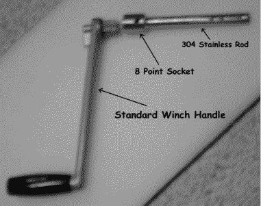 The roller-rod is relatively
simple to make. It consists of two parts welded together then a few holes. Note
that the holes in the front socket end are only for draining water and the
others are for the pin and nylon bushing pin. The nylon bushing pin must be
removable or the boom will not be ably to be removed from the mast.
The roller-rod is relatively
simple to make. It consists of two parts welded together then a few holes. Note
that the holes in the front socket end are only for draining water and the
others are for the pin and nylon bushing pin. The nylon bushing pin must be
removable or the boom will not be ably to be removed from the mast.
First I bought the winch handle, ($25.00), then I went to a Sears store and
matched a socket to fit. It was an 11/16", 8 point socket, ($4.50). I
thought a 3/4" socket was the correct size so maybe I got a metric wench
handle. Originally I wanted to find a stainless steel socket but could not find
one anywhere! Next I purchased 8" of 5/8" diam. 304 stainless steel
rod, ($12.50 at Metal Express. A small quantity industrial metal supply store).
From here I just welded the socket and rod together as you see in the picture.
Cutting the socket end off and turned a smooth spot at one end with a metal
lath, I then welded the two parts together. (That was done so the handle would
snap and lock in the rod section just like it does on winches.) Then I welded
all the parts together plus drilled 1/4" holes through the socket, for
water drainage, and three times at the opposite end of the rod. Two for anti
boom roll pin and the last one for the attachment to the boom itself. The
anti-roll pin holes act identical to the stock unit except the pin was now
located behind the mast instead of in front as the factory had originally done.
Now it was time to modify the hole in the mast itself. I obtained 8" of
1-1/4" diameter, 304 stainless tubing, about 8" of SS 3/4"diam.
SS tubing and about a foot of 1/2" wide 1/16" thick SS flat stock.
With these parts I replicated the "winged tube" portion that comes
stock from the factory except I used about 2" of 1-1/4" tube in the
front portion so the socket could be recessed. Then I welded both of them
together.
After calling the factory and talking with several other sailboat owners, I
decided a 1-1/4" diam. hole in both front and back would weaken the mast
too much. After some evaluations I figured that one larger hole in the front
would not weaken the safety limits of the mast much at all. The mast's rear
section hole was not altered at all. I carefully filed the front hole larger to
accept the 1-1/4" portion of tube and being sure to keep it centered.
The furthest aft 1/4" hole is used to hold the boom and universal on. A
quick release pin can be removed and allow the boom to be stored below while
trailering.
Except for the socket everything is 304 stainless steel to slow any rusting,
even the weld. The only reason the socket is not SS is because I couldn't find
any common to the market. (I suppose a phone call to a winch manufacture would
do.) The quality of most mechanic's sockets are pretty good so a little rust is
something I'll have to live with.
Let's hope my tall-mast never breaks in that spot! *(Note: Since the original
time of writing I've twice been In 30 knot winds and everything worked just
fine.)
It really sounds difficult but it isn't! For those who don't weld, (I do
regular welding not the fancy stuff), my friend who has for over thirty years,
told me it would take about 20 minutes to do the welding only. At around $80
per hour it should only run about $20 to $25 dollars. You have to supply the
metal and shaping.
Parts List:
| Description |
Quantity |
Aprox. Price
(Year=2001) |
| Winch Crank Handle. (On sale at West Marine.) |
1 |
$25.00 |
| 11/16" Eight Point Socket. (From Sears tool dept.) |
1 |
$4.50 |
| 5/8" diam., 304 Stainless Steel Rod. |
8" |
$12.00 |
| 1-1/4" 304 Stainless Steel Tube. |
2" |
$3.00 |
| 3/4" 304 Stainless Steel Tube. |
8" |
$5.00 |
| 1/16" x 1/2" x 8" 304 Stainless Steel (Cut in 4"
pieces). |
1 |
$4.00 |
| Quick Release Pin for Nylon Bushing. |
1 |
$4.00 |
| Machine work and welding by friends. |
1-2 hr. |
(Case of beer. About $10.00) |
| Total Cost about |
|
$70.00 |
Another Method - Steve's Boom Roller

Here is Steve's boom roller, it's got all lines going
aft. This way he doesn't need to leave the comfort of his cockpit making this a
safe and smart way to handle things!
His method entails a different modification at the gooseneck than my way.
Where I designed nothing to reach out forward, he designed a line spool to fit
on the roller rod. Check out the pictures.
I like the "all lines lead aft" that he did on his boat! (Last I
heard, he can have one built for you!)
Line Cleaning
Take care of your line. Don't let things like dirt,
build up on it. Gather it, put it in a mesh bag, then wash it on the gentle
cycle, (you can even use fabric softener). If not that way, soak it in fresh
water and mild soap. After it's clean, hang it up to dry.
Upper Forestay Mast Slot
The next time you inspect your upper forestay mount,
look to see if the "bar" is wearing on the mast slot. Do to a couple
reason's, mast rake being the biggest, it's possible to have the forestay pull
the upper bar mount, and rub on the mast slot. A quick visual check will tell.
A simple fix would be to file the slot longer. While your in the area, don't
forget to inspect the through bolt . It could be bent too. If it is, replace it
with new stainless steel bolt. I did and added compression tubes on both sides
of the bar. That now permits me to get a proper tightening and not crush the
mast itself. In addition, the preloaded bolt resists bending much more than the
stock setup bolt.
*Any bent bolts are inherently weaker and should never be straightened for
reuse.
A-model & C-model Mast Comments
My dealer made the mistake of giving me a
"C" tall mast and shrouds with my "A" tall mast sailboat.
The mast is the same 30 feet long but is mounted on a slightly higher
tabernackle. The forestay was a couple inches off and the lowers were also.
The forestay was corrected by adding a couple inches of hardware below the
furler. The lowers on the "C" model mount on the side of the cabin
and are about 7" shorter than what's used on the "A" model.
After talking with the factory, they sent me the correct shrouds.
In my opinion, the jib sheet was cut for a seven inch higher block but the
factory claims that sails for both are the same. 'Short of a re-cut sail, a new
set of jib travelers might do the trick, (which is what I did at a later time.)
Easy Jib Removal
Concerns about road grim and sun UV made me look for ways to
remove the entire foresail while land bound. If I could only find a good way to
detach both upper and lower sections all would be set, so I kept looking and
found a way!
Upper mount.
A standard pin using a cotter key was used to attach the upper furler to the
mast. That was way to bothersome. Having to undo and replace the cotter key
just to remove the holding pin! With all the hardware supplies on the market I
figured something would do, I just had to find it. After hunting around, I
found a wide-clevis that would fit the bill. Either 1/4" or 5/16"
size will work just fine. Now I can quickly remove the upper section by
unscrewing the pin.
The only modifications I did to the wide-clevis was to weld a small
stainless steel tab on the pin so my fingers could unscrew the pin without
needing a set of pliers. (Look carefully at picture on right.) The placement
and removal will always be on land so I doubt if I'll ever loose my custom pin,
but I do wish someone could make a captive wide-clevis.
All I have to remember now is to attach the upper furling unit before I
start stepping the mast. But I would never do something that dumb! (Blush!)
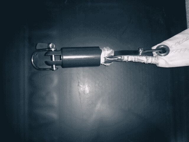
Lower mount.
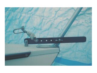
The left picture shows the lower furler mount. For lack of a
better name I call it a knife-switch. *(It reminds me of those big electrical
knife-switches used in the old Frankenstein movie.)
On the knife-switch I attached two stainless brackets and a 2,000 pound
working load chain link. (See left picture.) Please note that you should get
the forestay tension set where you want it before fully crimping the chain link
permanently on to the aluminum bar. It's not expensive to replace but if you do
crimp it tight on the bar then want to replace or move it you've just added 15+
minutes to the project.
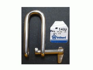
On the bottom of the Harkens furler is where I attached a Wichard clevis. It
allows for a quick disconnect.
If your wondering, it's a 1/4" Wichard #1433 captive pin clevis (seen
on the right). It's listed with a 1430 pound safe working load but I've found
that the forestay never goes that high even in a 30 knot blow!
Mast's Lower Shroud Attachment
A couple owners experienced a broken mast. Not a good
thing! It seems that the upper end of the lower shrouds has a "ball"
end, (looks like the end of a motorcycle cable). This is secured directly into
the spreader bar a couple inches out from the mast.
According to the factory, the problem arises when aftermarket shrouds are
used. Owner, Steve M. says the ball ends are, "an accident waiting to
happen" no matter who makes them, so why not change them now.
Several owners have gone to a much stronger through-bolt setup. (I was told
the factory switched on later models). If you choose this method you'll notice
that it is attached just like the upper shroud's are to the mast. The new
mounting position is located just below the spreaders.
Mast Through Bolt Warning
When you tighten those or any other mast bolt,
remember not to "squash" the mast. Owner "Koviatt99"
suggests using a compression fitting to prevent that possibility. (I did and
find it's great to properly tighten the bolts!)
He suggests using aluminum or stainless tubing. It kind of looks like a long
washer that goes through the entire mast.
First drill the mast to accept the compression fitting tube. The tube must
be near-flush with both sides of the mast. Place one shroud on the bolt, then
install the tube on the bolt and carefully insert it through the mast. Set the
second shroud on the bolt end and fasten everything together.
*The compression fitting tube will also strengthen the bolt assisting in
preventing it's bending. A similar compression fitting setup can be used on the
upper forestay mount. Just remember you need two shorter compression fittings
up there, one each side of the forestay anchor-bar, otherwise assemblage is the
same.
Spreader Bar Warning
The factory claims that the older models used
non-hardening spreader bars. Although they have replaced most in question with
the hardened type, not all have been exchanged.
Steve M. had a stainless steel bar made to replace the aluminum one. (I
believe he has more if you wish to acquire one from him.) Something to think
about.
Coated Cable Warning
Although not recommended by the factory, should you
decide to use vinyl coated shrouds, the factory suggests changing them more
often than standard shrouds. If the section near the turnbuckle starts to looks
bad, a rule-of-thumb is to replace them each four years if you sail in salt
water, and every ten years if in fresh water.
Harkens Furler-line Warning
During the first year, I replaced the Harkens furling
unit's line using smaller 3/16" line. This was done so I could use neat
colors to distinguish lines and for a larger capacity for my "future"
genoa, (in my dreams!). The only problem was that the smaller diameter line
kept wrapping below the spool and getting caught.
Trying several things to fix this, nothing seemed to work, I was about to
switch back to the original 1/4" line until I came up with using little
nylon tie-wraps. Placing them on the unit, they hold the line up so it wouldn't
get caught underneath. The tie-wraps acted sort-of-like a fishing reel by
holding the line up. No problems since!

Return to Home Port.
Mail to: The WebCaptain1@yahoo.com